This is simple radio receiver project which is capable to receive aviation radio voice signals which are transmit between 118MHz to 138MHz in AM (A3E). We got initial idea of this project by reading Sverre Holm’s (LA3ZA) article about "cheap VHF receiver project". Like LA3ZA’s original article this project is also based on Samsung’s KA22429 FM radio receiver IC.
KA22429 is low voltage FM radio receiver system developed by Samsung for portable radio receivers and as described by Holm’s it can push into VHF region by changing few values in its original circuit. In this project we redesign the schematic and PCB with some of those changes and now it can directly tune into aviation band with minimum number of adjustments.
The dimension of PCB of this receiver is 70mm × 45mm and all the components except KA22429 are standard through-hole type.
For the optimal results we recommended to use high gain audio power amplifier and good external antenna with this receiver. During prototyping / testing, we drive this system with 5V DC power supply and also connect this receiver to TDA2050 AF power amplifier. At our testing we got very successful results on 124.900MHz (Colombo Airways Center), 119.100MHz (Colombo/ Ratmalana Approach) and 118.100MHz (Colombo/ Ratmalana Tower). The recorded sample on 124.900MHz using this receiver is available in here.
The schematics, PCB design and wiring diagrams of this receiver are available to download at google drive.
KA22429 is low voltage FM radio receiver system developed by Samsung for portable radio receivers and as described by Holm’s it can push into VHF region by changing few values in its original circuit. In this project we redesign the schematic and PCB with some of those changes and now it can directly tune into aviation band with minimum number of adjustments.
The dimension of PCB of this receiver is 70mm × 45mm and all the components except KA22429 are standard through-hole type.
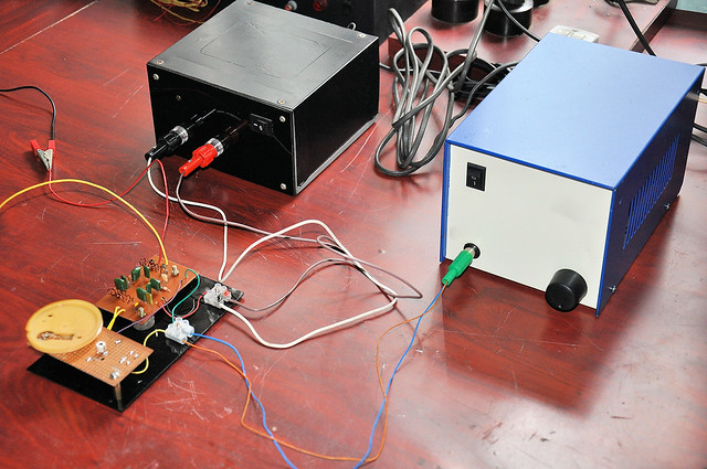 |
| KA22429 testing setup with 5V PSU and AF power amplifier. |
For the optimal results we recommended to use high gain audio power amplifier and good external antenna with this receiver. During prototyping / testing, we drive this system with 5V DC power supply and also connect this receiver to TDA2050 AF power amplifier. At our testing we got very successful results on 124.900MHz (Colombo Airways Center), 119.100MHz (Colombo/ Ratmalana Approach) and 118.100MHz (Colombo/ Ratmalana Tower). The recorded sample on 124.900MHz using this receiver is available in here.
The schematics, PCB design and wiring diagrams of this receiver are available to download at google drive.
Comments