In the last few days, we are looking for some simple FM radio receiver to integrate into one of our ongoing projects. For that, we try several FM radio receiver ICs including TDA7000, CD2003/TA2003/TA8164, CXA1019, and KA22429. Out of all those chips we select CD2003 (or TA2003/TA8164) based receiver for our project because of its simplicity and outstanding performance. Except to CD2003, Sony CXA1019 also perform well but we drop it because of its higher component count.
We design our receiver based on Toshiba TA2003 datasheet and later we try TA8164 and CD2003 with the same circuit. Either CD2003 or TA8164 can directly replace TA2003 IC, and as per our observations, TA8164 gives excellent results out of those 3 chips.
The PCB design and schematic which we used in our prototype project are available to download at google drive (including pin-outs of crystal filters and inductors).
Except for CD2003 IC, this receiver consists of 12 components. Three inductors used in this receiver are home-produced and all the winding details are available with the schematic diagram. This component count can also reduce by introducing FM bandpass filter module to the FM RF input stage of TA2003 chip. We try BPW85 FM bandpass filter with this circuit and it also gives the same results as original circuit.
In our testing, we operate this receiver using the 3.3V power supply and by average it draws 8mA - 12mA current from PSU.
To drive a speaker(s), this receiver needs to connect with suitable AF power amplifier and in our testing, we use a TDA2050 base AF power amplifier with this receiver.
We design our receiver based on Toshiba TA2003 datasheet and later we try TA8164 and CD2003 with the same circuit. Either CD2003 or TA8164 can directly replace TA2003 IC, and as per our observations, TA8164 gives excellent results out of those 3 chips.
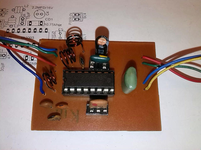 |
| A prototype version of CD2003 FM radio receiver |
The PCB design and schematic which we used in our prototype project are available to download at google drive (including pin-outs of crystal filters and inductors).
Except for CD2003 IC, this receiver consists of 12 components. Three inductors used in this receiver are home-produced and all the winding details are available with the schematic diagram. This component count can also reduce by introducing FM bandpass filter module to the FM RF input stage of TA2003 chip. We try BPW85 FM bandpass filter with this circuit and it also gives the same results as original circuit.
In our testing, we operate this receiver using the 3.3V power supply and by average it draws 8mA - 12mA current from PSU.
To drive a speaker(s), this receiver needs to connect with suitable AF power amplifier and in our testing, we use a TDA2050 base AF power amplifier with this receiver.
Comments