
SL414 Vintage power amplifier IC

SL414 is combined audio preamplifier and power amplifier IC manufactured by National semiconductors in early days. This amplifier is designed to operate in 10V to a 20V range and deliver 3W (R.M.S) audio output power into the 7.5Ω load. The frequency bandwidth of this IC is between 30Hz to 18kHz and with the 8Ω load, it produces 0.5% T.H.D on 3W.

The most uncommon feature of this IC is its EP-10 package. This EP-10 package is common to most of the SL4xx series amplifiers and thanks to its inbuilt screw it is really easy to attach heat-sinks to these ICs.
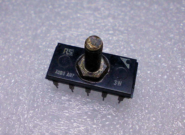
EP-10 package of SL414 audio amplifier IC.

During our prototyping, we try several SL414 amplifiers and most of them give quite satisfactory results to us. Link to most stable SL414 design is available at the bottom of this article. As per our experiments, to archive best results it is mandatory to build this amplifier on PCB with screened wires. Also to get the good results to make sure to drive this amplifier with a regulated DC power supply. In our tests, we use an LM317 base PSU to drive this amplifier.
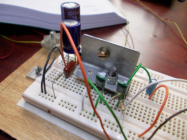
SL414 Amplifier prototype.

SL414 is quite hard to find and no longer manufactured by National (now TI). For those who having SL414’s can try our design/ PCB which is available at google drive.

Comments

Chinthaka said…
IC available @ Silvertones in Colombo, Sri-Lanka. if anybody is interested.

Popular posts from this blog

Building the TD4 4-Bit CPU

The TD4 is a famous 4-bit CPU featured in the book How to Build a CPU by Kaoru Tonami . The book focuses on constructing a functional processor entirely from basic 74-series TTL logic ICs. While the book is unfortunately only available in Japanese, a friend from Japan sent me a copy along with a TD4 PCB. I believe the PCB is based on the open-source design files available on BG5DIW's GitHub repository . "How to Build CPU" book and the PCB. Recently, I finally found the time to build and experiment with it. The project took a few months, as I had to translate the book myself to grasp the core concepts. The overall design is simple and elegant, offering a set of 12 instructions and a 16-byte ROM (implemented via DIP switches) for programming. The board operates on 5V and can be powered via USB. Most components were sourced from local shops, though I had to order a few 74HC-series ICs online. Later, I tested the circuit by replacing some 74HC components with 74LS series...

CD2003 - yet another simple FM radio receiver

In the last few days, we are looking for some simple FM radio receiver to integrate into one of our ongoing projects. For that, we try several FM radio receiver ICs including TDA7000, CD2003/TA2003/TA8164, CXA1019, and KA22429. Out of all those chips we select CD2003 (or TA2003/TA8164) based receiver for our project because of its simplicity and outstanding performance. Except to CD2003, Sony CXA1019 also perform well but we drop it because of its higher component count. We design our receiver based on Toshiba TA2003 datasheet and later we try TA8164 and CD2003 with the same circuit. Either CD2003 or TA8164 can directly replace TA2003 IC, and as per our observations, TA8164 gives excellent results out of those 3 chips. A prototype version of CD2003 FM radio receiver The PCB design and schematic which we used in our prototype project are available to download at google drive (including pin-outs of crystal filters and inductors ). Except for CD2003 IC, this receiver consist...

Arduino superheterodyne receiver

In this project, we extend the shortwave superheterodyne receiver we developed a few years ago . Like the previous design, this receiver operates on the traditional superheterodyne principle.  In this upgrade, we enhanced the local oscillator with Si5351 clock generator module and Arduino control circuit. Compared to the old design, this new receiver uses an improved version of an intermediate frequency amplifier with 3 I.F transformers. In this new design, we divide this receiver into several blocks, which include, mixer with a detector, a local oscillator, and an I.F amplifier. The I.F amplifier builds into one PCB. The filter stage, mixer, and detector stages place in another PCB. Prototype version of 455kHz I.F amplifier. In this prototype build, the Si5351 clock generator drives using an Arduino Uno board. With the given sketch, the user can tune and switch the shortwave meter bands using a rotary encoder. The supplied sketch support clock generation from 5205kHz (tuner f...