
Reel to reel tape cleaner

Due to the advancement of audio technologies reel to reel audio tapes are now classified as a rare item. The biggest problem with the reel to reel tapes is a fungus. The fungus is developed on old unused tapes due to humidity exposure. Also, another problem with old tapes is that the lubrication on the surface of the tape starts to deteriorate and tape starts to stick to itself, and this leads tape to break during the playback. Most of them that have Fungus can be fixed by using a tape cleaner. But these days reel to reel tape cleaners are not available to buy and because of that, we decided to build simple tape cleaner by using parts of old reel to reel tape players.

The core component of this player is an induction motor which we got from an old reel to reel player. The motor which we used in this project is the Sony HC-134. HC-134 is 100V single-phase, capacitor run, induction motor with 1500 - 1800 RPM. Recommended auxiliary winding capacitor for this motor is 1.5μF. To deliver 100V AC to motor we use 3A, 230V to 100V step-down transformer.
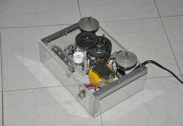
Final view of the reel to reel tape cleaner.

Casing and most of the parts of this cleaner is made by using 5mm transparent acrylic sheets. Size of the casing which we made for this cleaner is 300mm × 100mm × 215mm.

To clean 360m long (polyester) tape this cleaner takes 4 to 5min.

Tape before and after cleanup with the cleaner.

High-resolution photographs of this reel to reel tape cleaner are available at my flickr.com page.

Comments

Popular posts from this blog

Building the TD4 4-Bit CPU

The TD4 is a famous 4-bit CPU featured in the book How to Build a CPU by Kaoru Tonami . The book focuses on constructing a functional processor entirely from basic 74-series TTL logic ICs. While the book is unfortunately only available in Japanese, a friend from Japan sent me a copy along with a TD4 PCB. I believe the PCB is based on the open-source design files available on BG5DIW's GitHub repository . "How to Build CPU" book and the PCB. Recently, I finally found the time to build and experiment with it. The project took a few months, as I had to translate the book myself to grasp the core concepts. The overall design is simple and elegant, offering a set of 12 instructions and a 16-byte ROM (implemented via DIP switches) for programming. The board operates on 5V and can be powered via USB. Most components were sourced from local shops, though I had to order a few 74HC-series ICs online. Later, I tested the circuit by replacing some 74HC components with 74LS series...

CD2003 - yet another simple FM radio receiver

In the last few days, we are looking for some simple FM radio receiver to integrate into one of our ongoing projects. For that, we try several FM radio receiver ICs including TDA7000, CD2003/TA2003/TA8164, CXA1019, and KA22429. Out of all those chips we select CD2003 (or TA2003/TA8164) based receiver for our project because of its simplicity and outstanding performance. Except to CD2003, Sony CXA1019 also perform well but we drop it because of its higher component count. We design our receiver based on Toshiba TA2003 datasheet and later we try TA8164 and CD2003 with the same circuit. Either CD2003 or TA8164 can directly replace TA2003 IC, and as per our observations, TA8164 gives excellent results out of those 3 chips. A prototype version of CD2003 FM radio receiver The PCB design and schematic which we used in our prototype project are available to download at google drive (including pin-outs of crystal filters and inductors ). Except for CD2003 IC, this receiver consist...

AVR-HV: High voltage programmer for AVR microcontrollers

When it comes to AVR microcontrollers the most common programming option is In-System Programming ( ISP ). ISP interface is easy to use but in some scenarios it is totally unusable. The most common scenario is with some wrong fuse bit values. For example if we program SPIEN or RSTDISBL fuse bits, AVR microcontrollers may not respond to any in-system programmer(s). To overcome these problems the next available option is high voltage programming mode. In High voltage programming mode, 12V programming voltage is applied to RESET pin of target AVR microcontroller and user can change configuration fuses of AVR MCU with minimum amount of risk. The only drawback in this mode is that target microcontroller must need to be removed from the board to reprogram. Most of the AVR high voltage programmers are expensive and difficult to find in ordinary electronic shops. As a solution we implement USB base high voltage parallel programmer for AVR microcontrollers and it allows programming, readi...