If you are an audio enthusiast and if you have multiple audio systems and speakers, you may definitely need to have a speaker selector switch. These switches allow you to route a audio signal through a switching system and distribute it to various speakers. Using this listener can select single amplifier – speaker combination through the switch. We mainly design this switch to share our speaker system with multiple audio amplifiers. We design this switch to handle 6 stereo audio channels.
This switch is based on PIC16F88 - 8bit MCU, ULN2803 Darlington transistor arrays and 12 DPCO relays. MCU is the core component of this switch and it control all relays, seven-segment display and store last channel in E2PROM memory and restore it during next power-up.
In this system all audio lines are switching using 12 DPCO relays. To get optimal results we recommended to use good quality relays with thus switch. In our prototype we use Omron G2R-2-24V relays and got excellent results. Listener can change channel by pressing the (J2) push button. To disconnect / mute the channel, hold down J2 push switch for 5 - 10 sec.
Due to simplicity of the design, we construct our prototype version of this speaker-selector in Perfboard. When constructing this circuit make sure to attach suitable separate heatsinks to LM317 and L7805 regulators. Also to get higher stability we highly recommend to place C7 (0.1MFD) capacitor in between Pin 5 and 14 of U1 (PIC16F88) MCU. For seven-segment display we use 20mm single digit common cathode red color SSD.
This speaker selector is an open hardware project, all it’s source codes and schematics are available to download at google drive and github.com. All it’s content are released under the terms of MIT and CC BY-SA licenses.
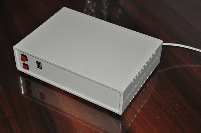 |
| Final view of 6 channel speaker selector prototype. |
This switch is based on PIC16F88 - 8bit MCU, ULN2803 Darlington transistor arrays and 12 DPCO relays. MCU is the core component of this switch and it control all relays, seven-segment display and store last channel in E2PROM memory and restore it during next power-up.
In this system all audio lines are switching using 12 DPCO relays. To get optimal results we recommended to use good quality relays with thus switch. In our prototype we use Omron G2R-2-24V relays and got excellent results. Listener can change channel by pressing the (J2) push button. To disconnect / mute the channel, hold down J2 push switch for 5 - 10 sec.
Due to simplicity of the design, we construct our prototype version of this speaker-selector in Perfboard. When constructing this circuit make sure to attach suitable separate heatsinks to LM317 and L7805 regulators. Also to get higher stability we highly recommend to place C7 (0.1MFD) capacitor in between Pin 5 and 14 of U1 (PIC16F88) MCU. For seven-segment display we use 20mm single digit common cathode red color SSD.
 |
| Speaker / amplifier connection terminals. |
This speaker selector is an open hardware project, all it’s source codes and schematics are available to download at google drive and github.com. All it’s content are released under the terms of MIT and CC BY-SA licenses.
Comments