This is 8 channel CMOS logic probe and pulsar which is useful when designing, testing and faultfinding in digital circuits. This circuit is designed using commonly available CMOS logic ICs which including a couple of 4069 hex inverters and 4040 binary counter.
The logic probe of this system is based on 4069 hex inverters and it indicates logic high and low states with 2 LEDs. Logic pulsar of this circuit is capable to generate 12 frequencies and highest frequency it can generate is 420kHz. This pulsar generates a square wave with 50% duty cycle and it's average rise time is 16µS.
Both schematic and PCB design of this logic probe and pulsar are available to download at google drive. In this schematic, all LED-L connections should connect to the anode of LEDs and cathode should be connected to the VSS terminal of J31 (LED-L-H) connector. All LED-H connections should connect to the cathode of LEDs and anode must be connected to VDD terminal of J31 (LED-L-H) connector.
In schematic LIN1 to LIN8 are logic probe inputs. All FREQ-CON-1 and FREQ-CON-2 connections should be connected to input terminals of the rotary switch and common terminal of the rotary switch should be connected to FREQ-CON-3 terminal. For the rotary switch, we recommended to use single pole 12 position rotary switch.
In our prototype, we use 3mm colored LEDs to indicate logic states and pulsar output. For the logic Low level, we use 3mm yellow LEDs and for the high level, we use 3mm green LEDs. To indicate pulsar output we use 3mm red LED. To drive the power supply we use 8V - 300mA step down transformer.
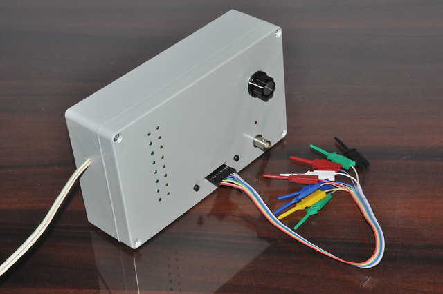 |
| A prototype version of 8 channel logic probe and pulsar |
The logic probe of this system is based on 4069 hex inverters and it indicates logic high and low states with 2 LEDs. Logic pulsar of this circuit is capable to generate 12 frequencies and highest frequency it can generate is 420kHz. This pulsar generates a square wave with 50% duty cycle and it's average rise time is 16µS.
Both schematic and PCB design of this logic probe and pulsar are available to download at google drive. In this schematic, all LED-L connections should connect to the anode of LEDs and cathode should be connected to the VSS terminal of J31 (LED-L-H) connector. All LED-H connections should connect to the cathode of LEDs and anode must be connected to VDD terminal of J31 (LED-L-H) connector.
In schematic LIN1 to LIN8 are logic probe inputs. All FREQ-CON-1 and FREQ-CON-2 connections should be connected to input terminals of the rotary switch and common terminal of the rotary switch should be connected to FREQ-CON-3 terminal. For the rotary switch, we recommended to use single pole 12 position rotary switch.
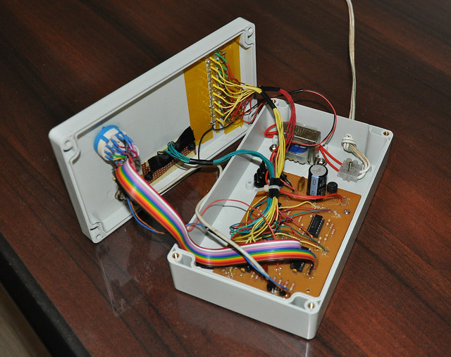 |
| Internal view of the prototype. |
In our prototype, we use 3mm colored LEDs to indicate logic states and pulsar output. For the logic Low level, we use 3mm yellow LEDs and for the high level, we use 3mm green LEDs. To indicate pulsar output we use 3mm red LED. To drive the power supply we use 8V - 300mA step down transformer.
Comments