This is an experimental stepper motor driver for Celestron CG-4 German equatorial mounts. This unit is functionally equivalent to the Celestron dual-axis motor driver, and we developed it as a replacement unit for the original Celestron driver.
The core component of this motor driver is PIC16F88 8-bit MCU. This MCU is responsible for driving two motors and scanning the user inputs. As an original unit, this system also got a clock driver for the right ascension (RA) axis.
This system uses two L293 motor drivers to drive the right ascension (RA) axis and declination (DEC) axis motors. This unit is designed to work with 6V bipolar stepper motors, which include in the telescope mount. The LM350 voltage regulator is used to maintain power to both stepper motors.
This replacement motor drive provides all the functionalities of the original unit, which including manual right-ascension and declination movement controls, speed, and direction controls.
We design this unit at the COVID-19 lockdown period, and therefore this prototype we used components which already available in our inventory. A component-wise this prototype is not an efficient design. The main objective of this design is to experiment with the motor driving mechanism and timing. Later we intend to design a more effective and feature-rich controller with the collaboration of digitspace.com.
The schematic and firmware source of this project is available at https://github.com/dilshan/eq-motor-driver.
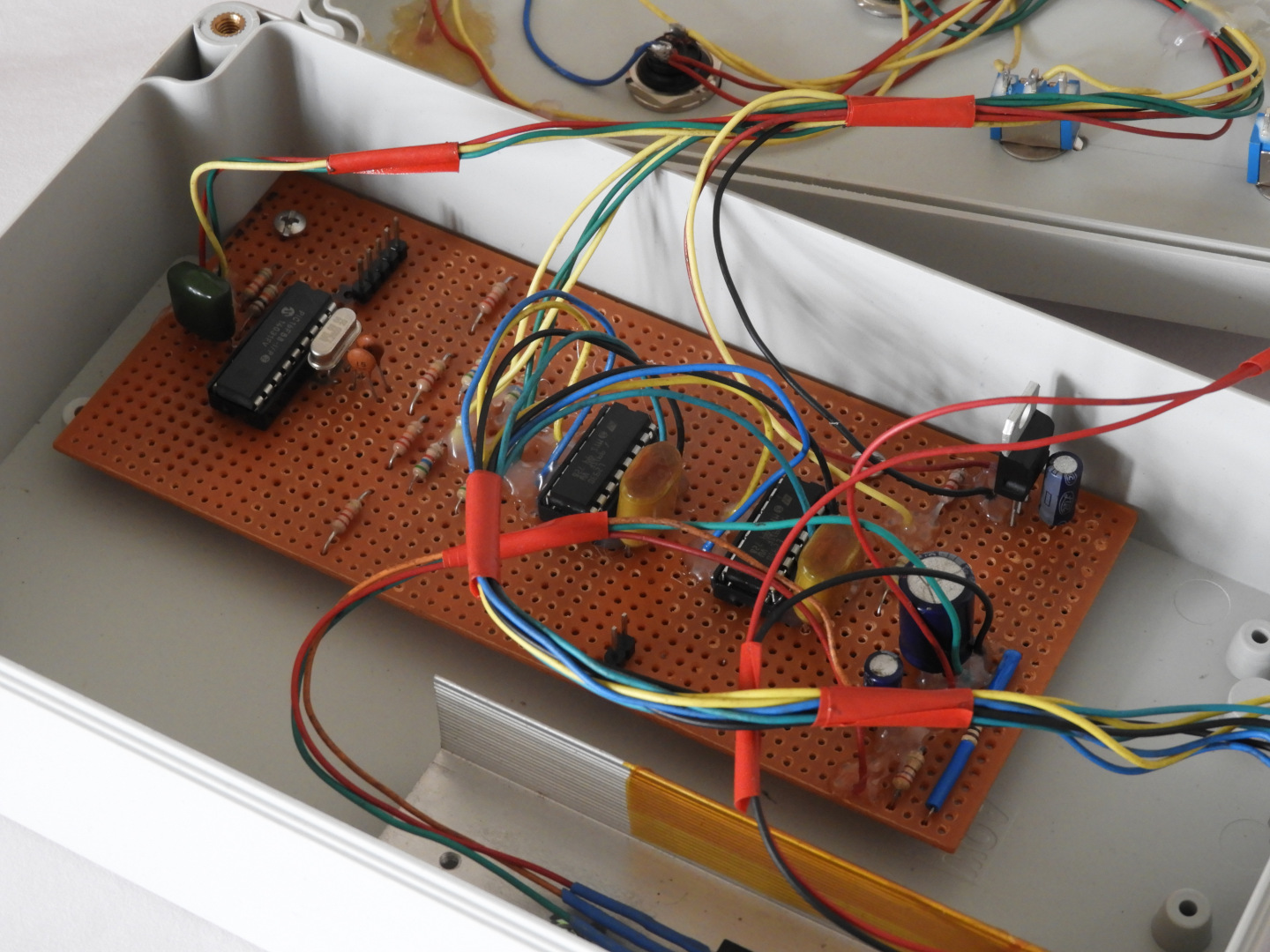 |
| The prototype circuit board of the motor controller unit. |
The core component of this motor driver is PIC16F88 8-bit MCU. This MCU is responsible for driving two motors and scanning the user inputs. As an original unit, this system also got a clock driver for the right ascension (RA) axis.
This system uses two L293 motor drivers to drive the right ascension (RA) axis and declination (DEC) axis motors. This unit is designed to work with 6V bipolar stepper motors, which include in the telescope mount. The LM350 voltage regulator is used to maintain power to both stepper motors.
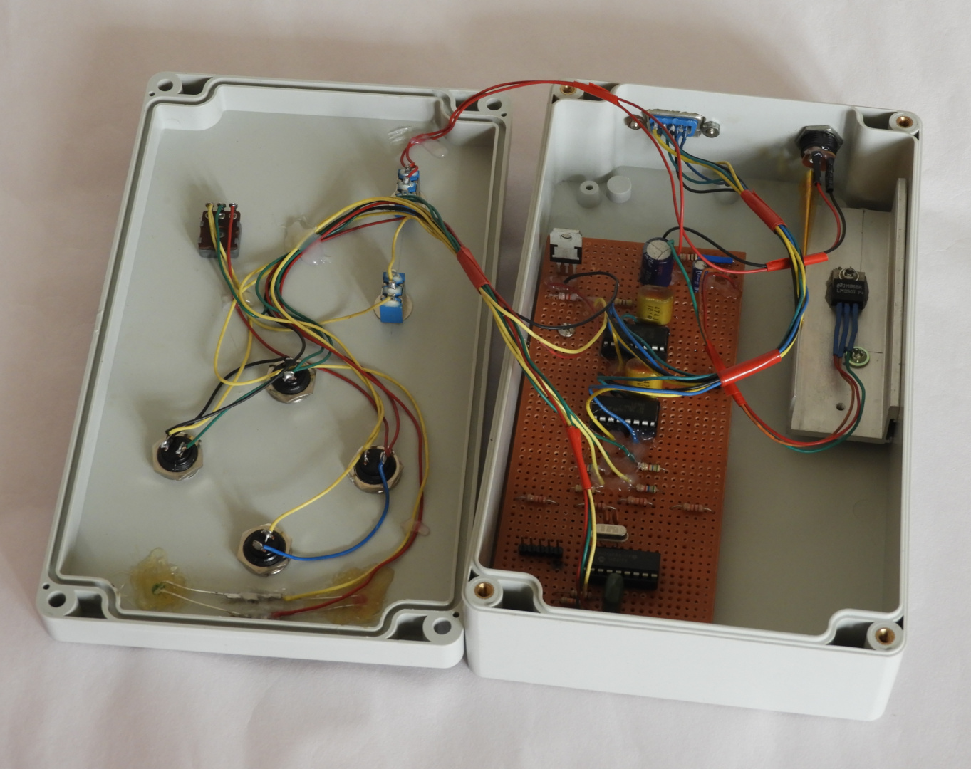 |
| Internal view of the prototype enclosure. |
This replacement motor drive provides all the functionalities of the original unit, which including manual right-ascension and declination movement controls, speed, and direction controls.
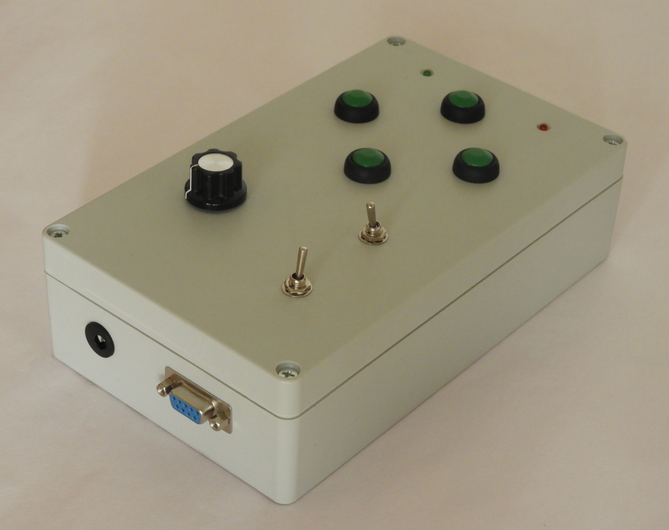 |
| Final view of the prototype unit. |
We design this unit at the COVID-19 lockdown period, and therefore this prototype we used components which already available in our inventory. A component-wise this prototype is not an efficient design. The main objective of this design is to experiment with the motor driving mechanism and timing. Later we intend to design a more effective and feature-rich controller with the collaboration of digitspace.com.
The schematic and firmware source of this project is available at https://github.com/dilshan/eq-motor-driver.
Comments