
A DIY UV exposure unit

UV exposure unit is a vital component in printing and mass-manufacturing industries. I decided to build a UV exposure unit to assist my screen-printing and PCB prototyping needs. After examining the market, I decided to construct this unit using black fluorescent tubes. Those black fluorescent tubes are usually available to purchase in many electrical shops here in Sri Lanka.

Finished UV exposure unit with four fluorescent tubes.

To drive the exposure unit, I build an electronic controller using ATtiny2313A MCU. This controller is capable to handle the exposure unit for up to 999 seconds (approximately 16 minutes). This electronic controller got two high-power relay driver stages, an audible notification unit, a safety lock, and a programmable timer.

The fluorescent tubes are drive using four separate chokes and starter units. For this unit, I use four NEC 20W - 60cm (T10) black fluorescent tubes.  12V, 5A SMPS is used to drive the relays and electronic controller unit.

PSU, control circuit board, chokes and starters used for this project.

Enclosure construction is the most time-consuming part of this project. It took nearly two and half months to finish the enclosure with all the fittings. Primarily, I build the enclosure using aluminum bars and aluminum composite panels. The dimensions of the enclosure unit are 74cm × 40cm × 19cm (with lid) / 15cm (without lid).

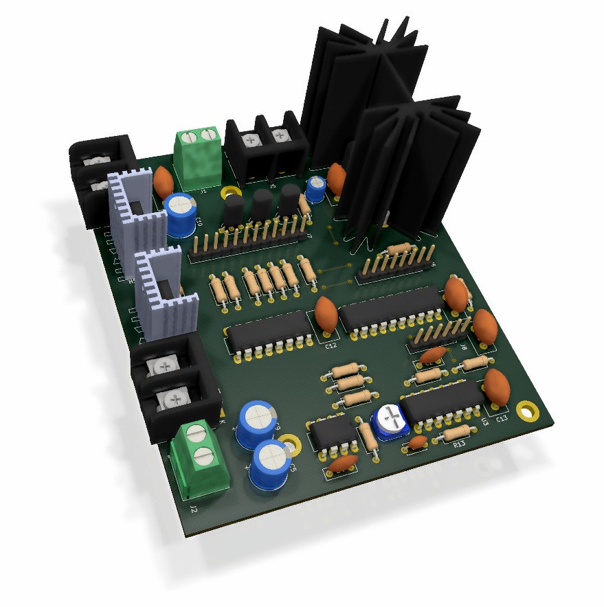
3D rendering of the controller PCB.

I exposed several paints and adhesives using this unit with higher success, including screen-printing photo emulsion paints and inks, several PCB protective coatings, etc. Usually, I use this unit to produce screen-printing screens and to fabricate PCBs for my prototyping projects.

The controller schematic, PCB design, firmware source code, and compiled firmware binaries of this exposure unit are available at my GitHub repository.

Comments

Popular posts from this blog

CD2003 - yet another simple FM radio receiver

In the last few days, we are looking for some simple FM radio receiver to integrate into one of our ongoing projects. For that, we try several FM radio receiver ICs including TDA7000, CD2003/TA2003/TA8164, CXA1019, and KA22429. Out of all those chips we select CD2003 (or TA2003/TA8164) based receiver for our project because of its simplicity and outstanding performance. Except to CD2003, Sony CXA1019 also perform well but we drop it because of its higher component count. We design our receiver based on Toshiba TA2003 datasheet and later we try TA8164 and CD2003 with the same circuit. Either CD2003 or TA8164 can directly replace TA2003 IC, and as per our observations, TA8164 gives excellent results out of those 3 chips. A prototype version of CD2003 FM radio receiver The PCB design and schematic which we used in our prototype project are available to download at google drive (including pin-outs of crystal filters and inductors ). Except for CD2003 IC, this receiver consist...

Arduino superheterodyne receiver

In this project, we extend the shortwave superheterodyne receiver we developed a few years ago . Like the previous design, this receiver operates on the traditional superheterodyne principle.  In this upgrade, we enhanced the local oscillator with Si5351 clock generator module and Arduino control circuit. Compared to the old design, this new receiver uses an improved version of an intermediate frequency amplifier with 3 I.F transformers. In this new design, we divide this receiver into several blocks, which include, mixer with a detector, a local oscillator, and an I.F amplifier. The I.F amplifier builds into one PCB. The filter stage, mixer, and detector stages place in another PCB. Prototype version of 455kHz I.F amplifier. In this prototype build, the Si5351 clock generator drives using an Arduino Uno board. With the given sketch, the user can tune and switch the shortwave meter bands using a rotary encoder. The supplied sketch support clock generation from 5205kHz (tuner f...

Experimental narrowband FM receiver for 2-meter band

This project is about MC3362 and ADF4351 based modularized, 2-meter narrow band FM receiver. In this design, the receiver splits into three modules as RF preamplifier, MC3362 tuner, and ADF4351 oscillator. The RF preamplifier builts around BF900 dual-gate MOSFET. The tuner stage builts using the popular MC3362 , low power narrowband FM receiver IC. For the oscillator, we use the ADF4351 DDS RF signal generator module. The core component of this receiver is MC3362 IC. This IC was designed by Motorola and is no longer in production, but this IC is still available to purchase in many online stores . The chip we used in this receiver was purchased from a local electronic component store for LKR 75 (USD 0.2). The RF preamplifier used in this receiver extracts from the N.Ganesan's (VU3GEK) LRR200, 2-meter band FM receiver project . Prototype version of the RF preamplifier. In this prototype, the above preamplifier was built as a module using a Manhattan construction technique. Th...