NTP based digital clock panel driver

This project introduces an open-source, ATmega328 based, configurable NTP clock with a 2.3-inch, 7-segment display driver. This clock automatically obtains time from the configured NTP server and updates the date and time of the built-in RTC (real-time clock). If the connection to the NTP server is lost, the clock continues to run using its built-in RTC.
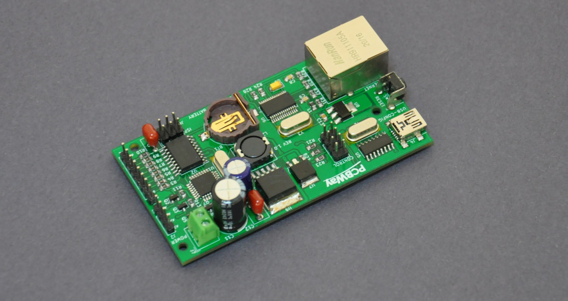
Finished NTP clock driver PCB.

All the parameters of this clock can configure using its USB base serial terminal. The firmware of this clock supports both static and DHCP addressing modes. Apart from that, parameters such as NTP server address, time-offset, and clock display formats can change through the menu-driven configuration terminal.

This clock is designed to drive large common-anode, 7-segment displays. The prototype version is assembled using four individual segments of 7.2V, 2.3-inch, red color displays (FJS23101BH). To archive, the necessary high output voltage and the current, the 7-segment display output stage of this clock is formed using ULN2803 Darlington transistor array and BC858 transistors.

The network component of this clock is built around the ENC28J60 10BASE-T stand-alone Ethernet controller.

Bottom side of the NTP clock driver PCB.

Highly accurate DS3231M RTC is using in this clock for time-keeping operations. To backup the date and time, the CR1220 type button cell is included in the PCB. The date and time are syncs with the NTP server during the system startup. Users can manually initiate synchronization by pressing the "SYNC" button in the system.

Depending on the NTP server, the user needs to specify the time offset to the system to get the correct local time. Time offset can configure using the system configuration menu, and it must be input in a standard format like +5:30.

Firmware of this clock is developed using the Arduino framework and libraries.

PCBWay provides sponsorship for this project. The PCBWay online ordering service provides excellent help to fabricate this PCB. We got finished PCBs within three days, and the quality of the service is at a superior level. PCB of this project can directly order from PCBWay through this link.
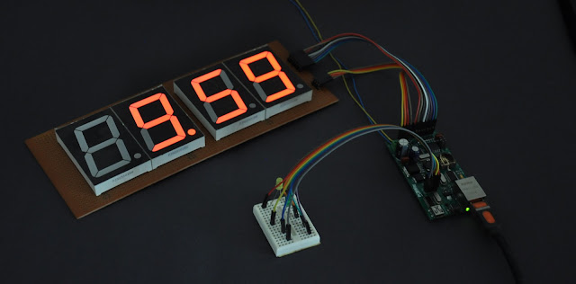
NTP clock driver test setup.

This project is an open hardware project. All the project source codes, schematic diagrams, documentation, PCB designs, and compiled firmware files are available in the project GitHub repository.

Comments

Popular posts from this blog

CD2003 - yet another simple FM radio receiver

In the last few days, we are looking for some simple FM radio receiver to integrate into one of our ongoing projects. For that, we try several FM radio receiver ICs including TDA7000, CD2003/TA2003/TA8164, CXA1019, and KA22429. Out of all those chips we select CD2003 (or TA2003/TA8164) based receiver for our project because of its simplicity and outstanding performance. Except to CD2003, Sony CXA1019 also perform well but we drop it because of its higher component count. We design our receiver based on Toshiba TA2003 datasheet and later we try TA8164 and CD2003 with the same circuit. Either CD2003 or TA8164 can directly replace TA2003 IC, and as per our observations, TA8164 gives excellent results out of those 3 chips. A prototype version of CD2003 FM radio receiver The PCB design and schematic which we used in our prototype project are available to download at google drive (including pin-outs of crystal filters and inductors ). Except for CD2003 IC, this receiver consist...

Arduino superheterodyne receiver

In this project, we extend the shortwave superheterodyne receiver we developed a few years ago . Like the previous design, this receiver operates on the traditional superheterodyne principle.  In this upgrade, we enhanced the local oscillator with Si5351 clock generator module and Arduino control circuit. Compared to the old design, this new receiver uses an improved version of an intermediate frequency amplifier with 3 I.F transformers. In this new design, we divide this receiver into several blocks, which include, mixer with a detector, a local oscillator, and an I.F amplifier. The I.F amplifier builds into one PCB. The filter stage, mixer, and detector stages place in another PCB. Prototype version of 455kHz I.F amplifier. In this prototype build, the Si5351 clock generator drives using an Arduino Uno board. With the given sketch, the user can tune and switch the shortwave meter bands using a rotary encoder. The supplied sketch support clock generation from 5205kHz (tuner f...

Calculator for audio output transformers

Audio output transformers are heavily used in a vacuum tube and some (older) transistor base audio power amplifiers, but these days output transformer are quite hard to find and expensive item. For homebrew projects, the best option is to construct those transformers by ourselves and this script helps to calculate winding parameters for those transformers. This " AF output transformer calculator " script is written using Python and it works with most of the commonly available Python interpreters . The script is available to download at google drive under the terms of GNU General Public License version 3.0 . Homebrewed 25k: 4 output transformer Once supplied the input parameters this script provides a winding ratio, the number of turns required for primary and secondary winding and required copper wire gauges for both primary and secondary windings, etc. We construct several AF output transformers based on results of this script, which including transformers for M...