
Arduino telephone caller ID unit

CLI, also known as Caller ID and calling number delivery (CND), is a service offered by the telephone service provider to customers to obtain the calling party number and date/time of the call. The service activation and information format of CLI are different from telephone network operator to operator.

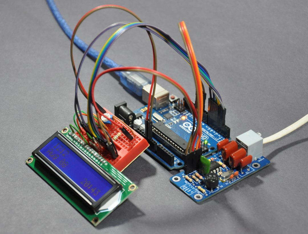
CLI display unit - minimum test setup

In this project, we will create a small Caller ID decoder using Arduino UNO and a custom-made HT9032D module.

The core component of the project is the HT9032D, which can decode incoming call ID data over a telephone connection. This IC supports Bell 202 FSK and ITU-T version 2.3 CLI protocol specifications.

The HT9032D module we created here base on the application example given in the IC datasheet. In addition to decoding CLI data, this module also can detect ring signal rises over the phone line.

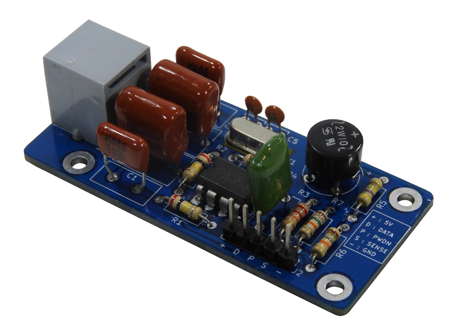
Assembled HT9032D module

The Arduino UNO is used to process the decoded CLI data stream and manipulate the LCD. In an idle state, the decoder and LCD are inactive. If the system detects the ring signal, the Arduino initiates data processing over the UART channel to locate the incoming CLI information. Successfully decoded data are display on the LCD screen. The Arduino sketch prepared for this project can handle the caller line ID, name, and date/time MDMF (Multiple Data Message Format) packet IDs. As we have observed, these MDMF IDs are found in nearly all CLI data streams.

The HT9032D module constructs in this project are consist of standard through-hole type components. No special soldering equipment is needed to assemble this module.

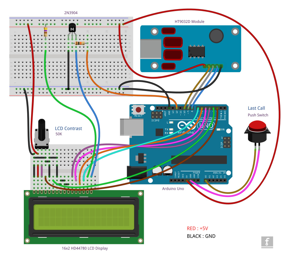
Complete wiring diagram of the CLI display unit

This system uses the popular 16×2 HD44780 character LCD panel to display captured/decoded CLI information. The whole circuit can build and test on a breadboard, as shown in the below video.

With SLT NGN value-added service, we tested this system on SLT (Sri Lanka Telecom) FFTH line, and all incoming calls were decode by this unit without any error. As we observe, the MDMF packet sent by SLT always consists of caller ID, name, and date/time parameters only. 

In this given wiring layout, the "last call" button is an optional add-on to display the last call information received to the system. Ignore this connection if you do not need this feature.

The LED connected to pin 13 (Arduino UNO onboard LED) indicates the missed call(s). Press the "last call" button to clear this indicator.

All schematics, source codes, and PCB design files related to this project can be download from the project repository at https://github.com/dilshan/arduino-caller-id. All the source codes in this project are released under the terms of the MIT License. The HT9032D module design files are released under the CERN-OHL-W Version 2.0 License.

Comments

Popular posts from this blog

CD2003 - yet another simple FM radio receiver

In the last few days, we are looking for some simple FM radio receiver to integrate into one of our ongoing projects. For that, we try several FM radio receiver ICs including TDA7000, CD2003/TA2003/TA8164, CXA1019, and KA22429. Out of all those chips we select CD2003 (or TA2003/TA8164) based receiver for our project because of its simplicity and outstanding performance. Except to CD2003, Sony CXA1019 also perform well but we drop it because of its higher component count. We design our receiver based on Toshiba TA2003 datasheet and later we try TA8164 and CD2003 with the same circuit. Either CD2003 or TA8164 can directly replace TA2003 IC, and as per our observations, TA8164 gives excellent results out of those 3 chips. A prototype version of CD2003 FM radio receiver The PCB design and schematic which we used in our prototype project are available to download at google drive (including pin-outs of crystal filters and inductors ). Except for CD2003 IC, this receiver consist

Arduino superheterodyne receiver

In this project, we extend the shortwave superheterodyne receiver we developed a few years ago . Like the previous design, this receiver operates on the traditional superheterodyne principle.  In this upgrade, we enhanced the local oscillator with Si5351 clock generator module and Arduino control circuit. Compared to the old design, this new receiver uses an improved version of an intermediate frequency amplifier with 3 I.F transformers. In this new design, we divide this receiver into several blocks, which include, mixer with a detector, a local oscillator, and an I.F amplifier. The I.F amplifier builds into one PCB. The filter stage, mixer, and detector stages place in another PCB. Prototype version of 455kHz I.F amplifier. In this prototype build, the Si5351 clock generator drives using an Arduino Uno board. With the given sketch, the user can tune and switch the shortwave meter bands using a rotary encoder. The supplied sketch support clock generation from 5205kHz (tuner frequ

Calculator for audio output transformers

Audio output transformers are heavily used in a vacuum tube and some (older) transistor base audio power amplifiers, but these days output transformer are quite hard to find and expensive item. For homebrew projects, the best option is to construct those transformers by ourselves and this script helps to calculate winding parameters for those transformers. This " AF output transformer calculator " script is written using Python and it works with most of the commonly available Python interpreters . The script is available to download at google drive under the terms of GNU General Public License version 3.0 . Homebrewed 25k: 4 output transformer Once supplied the input parameters this script provides a winding ratio, the number of turns required for primary and secondary winding and required copper wire gauges for both primary and secondary windings, etc. We construct several AF output transformers based on results of this script, which including transformers for M