The LM386 is a low-voltage audio power amplifier designed by National Semiconductor, which is now part of Texas Instruments. Introduced in 1983, it has been widely used in various audio applications, such as amplifying signals in small radios, portable speakers, and other low-power audio equipment. This compact device integrates all the essential components of a basic audio amplifier circuit, including an internal biasing network, an input stage, and an output driver.
It operates within a supply voltage range of 4V to 12V, making it ideal for driving small speakers while consuming minimal power. A standout feature of the LM386 is its adjustable gain, which can be varied between 20 (26dB) and 200 (46dB) using external components.
 | |
| Assembled LM386 power amplifier. |
Although modern Class-D amplifiers offer higher efficiency and greater power output, the LM386 remains a viable solution in certain applications due to its straightforward design, low cost, ease of assembly (thanks to its through-hole packaging), and purely analog architecture.
The LM386 is particularly well-suited for battery-powered and portable audio devices, including hobbyist audio projects, intercom systems, TV and radio tuners, sound effects applications, and signal generation circuits.
Throughout the years, numerous variants of the LM386 have been created to meet various needs and specifications. Below are some of the widely available variants along with their specialties:
- LM386 and LM386N-1 (standard version): Works with 4V to 12V. It delivers typically 0.125W to 1W audio output power, depending on the supply voltage and load. The operating temperature ranges from 0°C to 70°C.
- LM386N-3: Although it is popular as an industrial-grade version, we cannot find any official sources to confirm this. The output power ranges from 0.5W to 0.7W. Except for output power, both N-1 and N-3 have identical characteristics.
- LM386N-4 (commonly available version): Works with 5V to 18V. It delivers typically 0.7W to 1W audio output power, depending on the supply voltage and load. The operating temperature ranges from 0°C to 70°C.
- LM386D: Similar to the standard LM386, it is often packaged in surface-mount configurations.
- LM386M: Both LM386M and LM386N are having same characteristics except package dissipation. The LM386N has a package dissipation of 1.25W, while the LM386M has a package dissipation of 0.73W.
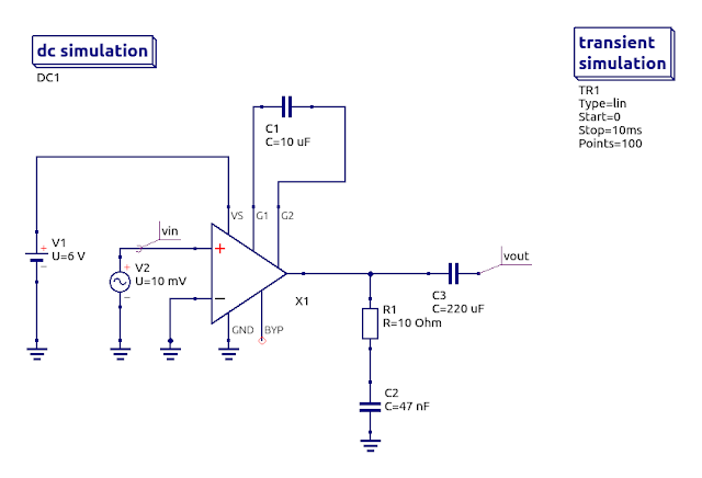
The amplifier’s default gain is set to 20, determined by an internal feedback network. To boost the gain to 46dB, an external capacitor, typically 10μF, is connected between pins 1 and 8. This configuration bypasses the internal 1.35kΩ resistor, resulting in a substantial increase in the amplifier's voltage gain.
 |
| LM386 in lowest 26dB gain setting. |
 |
| Simulation result of above setup with 10mVpp source. |
The Simtelic KT0001 - LM386 power amplifier kit is designed to simplify gain adjustments, and I frequently use several of these kits in my experiments.
For gain adjustment, the R1 (in PCB) resistor should vary from 0Ω (providing the maximum gain of 46dB) to approximately 10kΩ.
 |
| Top view of the assembled Simtelic LM386 power amplifier. |
The external resistor for the LM386 can be calculated using the following formula:
\begin{equation} R1= \frac{2 \cdot R_{i5} - (\text{Gain} - 1) \cdot R_{i3}}{\text{Gain} - 1} \end{equation}According to the datasheet, Ri3 = 150Ω and Ri5 = 15kΩ.
For instance, by placing a 150Ω resistor in the R1 position (in PCB), a gain closer to 100 is achieved.
 |
| Setting up the gain to 100 in spice simulation. |
 |
| Simulation result of above setup with the same 10mVpp source. |
It is important to note that increasing the gain to 200 (46dB) can make the amplifier more prone to oscillations. To enhance stability, a small resistor (e.g., 10Ω) should be placed in series with the capacitor between pins 1 and 8.
 | |
| LM386 with maximum gain setting. |
 |
| Simulation result of above setup with the same 10mVpp source. |
 |
| Actual output from assembled LM386 kit with gain set to 200. |
Using higher gain settings with a 12V power supply may lead to increased heat dissipation, which requires careful thermal management. For better performance and durability, it is advisable to operate this small amplifier at or below 9V.
The LM386 continues to be in production and is readily available for purchase both online and in many local electronics stores. This amplifier remains an excellent choice for beginners in the field of electronics. Simtelic offers the PCB and the complete unsoldered kit, available for direct purchase.
The Qucs / Ngspice simulation files referenced in this article can be accessed from: https://gist.github.com/dilshan/a34e1c68912c8b4c6e8df44f33986783.
Comments