This blog post discusses the engineering design, construction, and performance evaluation of a 4-element Yagi-Uda antenna specifically optimized for the 2-meter amateur radio band, focusing on the frequency range of 144MHz to 145.5MHz. The project was initiated to establish strong and reliable communication with distant VHF repeaters of the RSSL (Radio Society of Sri Lanka), which are located approximately 58km and 96km from my location.
 |
| The finished antenna, oriented towards the Yatiyantota repeater. |
The primary objective was to develop a high-gain, directional antenna with a superior front-to-back ratio. This directionality is essential for maximizing signal capture from the desired repeater while minimizing interference and noise from unwanted directions, ultimately improving the SNR and the quality of the communication link.
VHF communication at these distances typically relies on line-of-sight propagation, making antenna gain a critical factor in overcoming path loss and achieving reliable signal levels.
 |
| 3D rendering of the antenna. |
The antenna design was carried out using MMANA-GAL, a well-known and validated software suite based on the Method of Moments (MoM) for antenna analysis. While MoM simulations require significant computational resources, they deliver accurate predictions of antenna performance. This is achieved by breaking down the antenna structure into small segments and solving Maxwell's equations to determine the current distribution. This approach enables precise modeling of antenna impedance, radiation patterns, gain, and front-to-back ratio.
Key design parameters were iteratively optimized within MMANA-GAL to achieve the desired performance:
- Target Frequency Band: 144MHz - 145.5MHz, encompassing the primary 2m amateur band frequencies.
- Characteristic Impedance: 50Ω, to ensure impedance matching with standard RG-58 coaxial transmission line and transceiver equipment, minimizing reflected power and maximizing power transfer to the antenna.
- Front-to-Back Ratio Optimization: Aiming for a high front-to-back ratio to minimize reception from the rear hemisphere, reducing interference and improving signal clarity, especially in noisy RF environments.
- SWR Minimization: Achieving a VSWR as close to 1:1 as possible across the target frequency band. Low VSWR indicates efficient impedance matching and minimal power reflection back to the transmitter.
 |
| Radiation pattern and performance chart. |
The simulation process involved adjusting the lengths of the elements and the spacing between them for the reflector, driven element, and directors of the Yagi antenna. This antenna operates on the principles of constructive and destructive interference of electromagnetic waves. The reflector, positioned behind the driven element, reflects waves forward, while the directors, located in front of the driven element, help to focus the radiated energy toward the main lobe. This arrangement increases both the forward gain and directivity of the antenna.
 |
| 3D view of the radiation pattern. |
The optimized design, after multiple simulation iterations in MMANA-GAL, predicted the following performance metrics:
- Simulated Gain: 13.1dBi. This represents a significant gain increase over a dipole antenna (approximately 2.15dBi) and translates to a substantial improvement in signal strength.
- Simulated Front-to-Back Ratio: 15.35dB. This indicates that the power radiated in the forward direction is over 15dB stronger than in the backward direction, providing good directivity and rejection of rearward signals.
- Simulated Input Impedance: Close to 50Ω across the 144MHz - 145.5 MHz band, ensuring a good match to standard 50Ω transmission lines.
 |
| Impedance, SWR, gain, and front-to-back ratio across a frequency range. |
The construction of the antenna focused on durability, lightweight design, weather resistance, and good electrical conductivity, all while keeping costs reasonable. We used 10mm diameter aluminum alloy tubes sourced from Lanka Aluminum. This diameter was selected because it is commonly available at many aluminum stores.
For the boom, we use a rigid 19.05mm (3/4 inch) square aluminum box bar, also sourced from Lanka Aluminum. This material is made from a similar aluminum alloy to ensure structural integrity and to serve as a common ground plane for the parasitic elements. The square profile enhances torsional stiffness compared to a round boom.
To effectively secure the components, we use 10mm ABS element holders. These holders are commonly utilized here to construct VHF/UHF TV antennas. Both the plastic holders and 10mm end caps are sourced from Kumarasinghe Radio.
 |
| Dipole assembly and feedpoint arrangement. |
The Polychrome junction box, measuring 85×85×50 mm and designed for outdoor use, is waterproof with an IP55 rating. This rating indicates that the box provides protection against dust ingress (although some dust may enter, it won’t cause harm) and shields against water jets from any direction. This makes it an essential choice for long-term outdoor deployment, ensuring the critical dipole feedpoint remains protected.
We used corrosion-resistant M3 stainless steel nuts, bolts, and washers to secure all elements and the IP box.
Precise assembly is crucial for achieving the intended performance of a Yagi antenna. All elements, except for the driven dipole, were directly and electrically bonded to the aluminum boom. This is a standard practice for Yagi antennas, as it utilizes the boom as a common ground, simplifying construction. Electrical connections were established using M3 stainless steel bolts that passed through pre-drilled holes in the aluminum tubes and boom, ensuring reliable electrical contact. The element holders provided mechanical support and maintained precise spacing between the elements, as well as a 90° angle with the boom, in accordance with the design specifications from MMANA-GAL.
 |
| Mounting the dipole on a boom using a 10mm acrylic strip (3D rendering). |
The IP55 box containing the dipole was securely mounted to the underside of the aluminum boom using M3 stainless steel fasteners. To ensure consistent height with other elements, we used a strip of 10mm acrylic sheet.
Antenna VSWR and input impedance were measured across the frequency range of 144MHz - 145.5MHz using a VNA. The measured SWR of 1.1 at 145.025MHz confirms excellent impedance matching at the desired operating frequency. A Smith chart, generated by the VNA, visually represented the antenna's impedance characteristics throughout the band. It demonstrated that the impedance remained close to the target of 50Ω, indicating a broadband match across the intended operating frequencies.
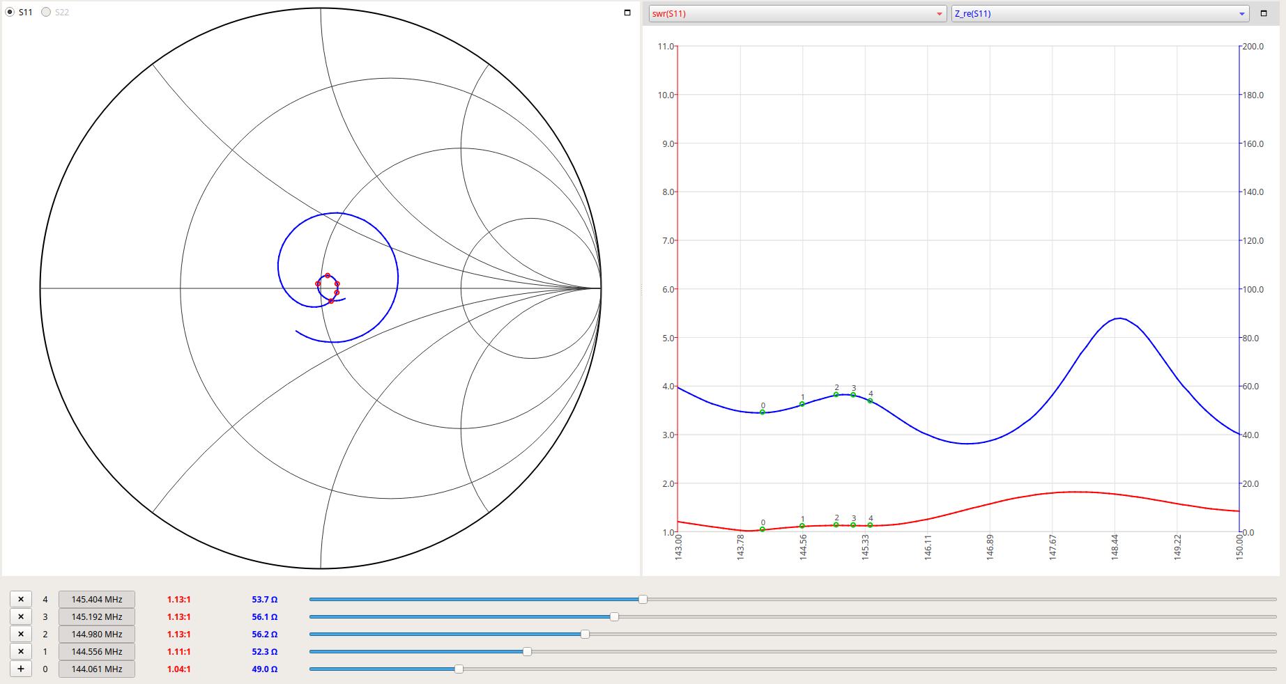 |
| Actual impedance and SWR measurements from the antenna. |
The antenna was deployed at the designated operating location and oriented towards the target RSSL VHF repeaters. A subjective performance evaluation was conducted by attempting communication with the repeaters at distances of 58km (Yatiyanthota) and 96km (Piduruthalagala).
Reports from repeater users consistently indicated an S9+ signal strength, showing a significant improvement in reception when compared to a baseline mobile whip antenna.
You can find the complete design of this antenna, including all dimensions, in the PDF linked here. The Fusion 360 design file for the antenna is also available here. Additionally, the MMANA-GAL design file (in .mma format) can be downloaded from this link.
Comments