HD-1410 is quite popular iambic keyer which is manufactured around the 1970s by Heathkit. The original HD-1410 keyer is designed using 5 commonly available 74LS series TTL ICs and 8 transistors. Other than iambic operation it has an option to adjust sidetone frequency and support for (external) single-paddle key unit.
In this project, we redesign the original HD-1410 electronic keyer with today's commonly available components. In this new design, the key components which we replace are transistors, diodes, and power supply section of the original HD-1410 circuit. Most of the NPN transistors in original design are replaced with KSP42 and KSP10 transistors, and all the PNP transistors are replaced with KSP92 transistors. To keep everything simple we also use the same TTL chip-set with this new design.
Tested PCB layout for this new keyer is available in the project archive and this PCB layout is based on standard through-hole type components. Dimensions of this PCB is 110mm × 102mm.
We test this modified HD-1410 design with several transceivers and it performs extremely well. This new design also behaves similar to original HD-1410 unit and the parameters which got change are DC input voltage range and power consumption only.
Schematic, PCB and wiring diagram of this modified HD-1410 keyer are available to download at google drive. The original Heathkit HD-1410 schematic and details are available at http://www.heathkit.nu/heathkit_nu_HD-1410.html.
In this project, we redesign the original HD-1410 electronic keyer with today's commonly available components. In this new design, the key components which we replace are transistors, diodes, and power supply section of the original HD-1410 circuit. Most of the NPN transistors in original design are replaced with KSP42 and KSP10 transistors, and all the PNP transistors are replaced with KSP92 transistors. To keep everything simple we also use the same TTL chip-set with this new design.
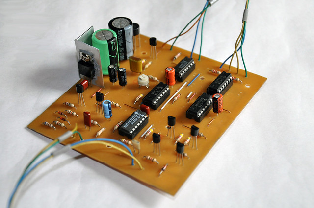 |
| PCB of modified Heathkit HD-1410 electronic keyer. |
Tested PCB layout for this new keyer is available in the project archive and this PCB layout is based on standard through-hole type components. Dimensions of this PCB is 110mm × 102mm.
We test this modified HD-1410 design with several transceivers and it performs extremely well. This new design also behaves similar to original HD-1410 unit and the parameters which got change are DC input voltage range and power consumption only.
Schematic, PCB and wiring diagram of this modified HD-1410 keyer are available to download at google drive. The original Heathkit HD-1410 schematic and details are available at http://www.heathkit.nu/heathkit_nu_HD-1410.html.
Comments