
Simple crystal tester

This is simple Colpitts oscillator to test commonly available passive crystals which range between 2MHz to 27MHz. This unit must connect to an oscilloscope and/or frequency counter to get the frequency of the crystal.

This circuit is designed to work around 9V to 12V DC power source. Both 2SC930 transistors can replace with any high-speed NPN transistor such as 2SC829, 2SC933, etc.

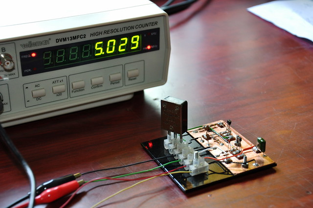
Testing 5030kHz FT-243 crystal using a prototype version of crystal tester.

In our lab, we use Manhattan-style layout to prototype this crystal tester and it produces highly accurate results with an above-specified frequency range. According to our observations, after 27MHz, the amplitude of the waveform starts to decrease steeply.

Schematic and Stripboard wiring layout for this crystal tester is available to download in here.

Comments

Popular posts from this blog

Building the TD4 4-Bit CPU

The TD4 is a famous 4-bit CPU featured in the book How to Build a CPU by Kaoru Tonami . The book focuses on constructing a functional processor entirely from basic 74-series TTL logic ICs. While the book is unfortunately only available in Japanese, a friend from Japan sent me a copy along with a TD4 PCB. I believe the PCB is based on the open-source design files available on BG5DIW's GitHub repository . "How to Build CPU" book and the PCB. Recently, I finally found the time to build and experiment with it. The project took a few months, as I had to translate the book myself to grasp the core concepts. The overall design is simple and elegant, offering a set of 12 instructions and a 16-byte ROM (implemented via DIP switches) for programming. The board operates on 5V and can be powered via USB. Most components were sourced from local shops, though I had to order a few 74HC-series ICs online. Later, I tested the circuit by replacing some 74HC components with 74LS series...

CD2003 - yet another simple FM radio receiver

In the last few days, we are looking for some simple FM radio receiver to integrate into one of our ongoing projects. For that, we try several FM radio receiver ICs including TDA7000, CD2003/TA2003/TA8164, CXA1019, and KA22429. Out of all those chips we select CD2003 (or TA2003/TA8164) based receiver for our project because of its simplicity and outstanding performance. Except to CD2003, Sony CXA1019 also perform well but we drop it because of its higher component count. We design our receiver based on Toshiba TA2003 datasheet and later we try TA8164 and CD2003 with the same circuit. Either CD2003 or TA8164 can directly replace TA2003 IC, and as per our observations, TA8164 gives excellent results out of those 3 chips. A prototype version of CD2003 FM radio receiver The PCB design and schematic which we used in our prototype project are available to download at google drive (including pin-outs of crystal filters and inductors ). Except for CD2003 IC, this receiver consist...

Arduino superheterodyne receiver

In this project, we extend the shortwave superheterodyne receiver we developed a few years ago . Like the previous design, this receiver operates on the traditional superheterodyne principle.  In this upgrade, we enhanced the local oscillator with Si5351 clock generator module and Arduino control circuit. Compared to the old design, this new receiver uses an improved version of an intermediate frequency amplifier with 3 I.F transformers. In this new design, we divide this receiver into several blocks, which include, mixer with a detector, a local oscillator, and an I.F amplifier. The I.F amplifier builds into one PCB. The filter stage, mixer, and detector stages place in another PCB. Prototype version of 455kHz I.F amplifier. In this prototype build, the Si5351 clock generator drives using an Arduino Uno board. With the given sketch, the user can tune and switch the shortwave meter bands using a rotary encoder. The supplied sketch support clock generation from 5205kHz (tuner f...