Audio Signal Generator (or AF Signal Generator) is often used in RF and AF base designing and experiments. In this article we introduce less complex AF signal generator based on commonly available electronic components. The heart of this AF signal generator is Intersil ICL8038 precision waveform generator/voltage controlled oscillator IC. ICL8038 is a function generator capable of producing sine, square and sawtooth waveforms at same time. In this project we combine ICL8038 with inverting and non-inverting amplifiers to get above mentioned 3 waveforms with 0° and 180° phase differences at the same time. Those inverting and non-inverting outputs help to use this AF signal generator with balanced audio systems.
The given schematic and PCB design of this AF signal generator contains ICL8038 waveform generator, inverting and non-inverting amplifier stage, output buffer and 12V regulated power supply. All the above mentioned modules are integrated into 65mm × 110mm PCB with standard through-hole type components.
This AF signal generator is design to work with 18V 500mA AC input. To increase the stability, we recommended using "audio grade coaxial cables" for all external connections except to power indicator LED.
This given design is capable to generate 200Hz to 10kHz sine, square sawtooth waveforms. It is possible to have some slight frequency drifts due to temperature variations in the operating environment.
As per our measurements and observations warm-up time of this AF signal generator is around 3 to 5minutes, but this can be varied based on the type of enclosure, component arrangements, external temperature, etc.
Schematic, PCB design and wiring diagrams of this AF signal generator is available to download at google drive. All these design files of this project are distributed under the terms of Creative Commons Attribution 4.0 International License (CC-BY-4.0). High resolutions photographs of this project are available at this flickr page.
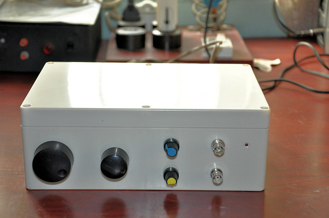 |
| Final version of AF signal generator. |
The given schematic and PCB design of this AF signal generator contains ICL8038 waveform generator, inverting and non-inverting amplifier stage, output buffer and 12V regulated power supply. All the above mentioned modules are integrated into 65mm × 110mm PCB with standard through-hole type components.
This AF signal generator is design to work with 18V 500mA AC input. To increase the stability, we recommended using "audio grade coaxial cables" for all external connections except to power indicator LED.
This given design is capable to generate 200Hz to 10kHz sine, square sawtooth waveforms. It is possible to have some slight frequency drifts due to temperature variations in the operating environment.
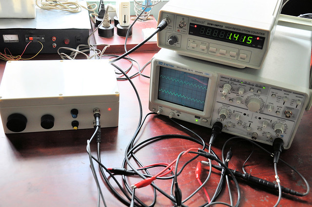 |
| Generating 1.415kHz sawtooth waveform using AF signal generator. |
As per our measurements and observations warm-up time of this AF signal generator is around 3 to 5minutes, but this can be varied based on the type of enclosure, component arrangements, external temperature, etc.
Schematic, PCB design and wiring diagrams of this AF signal generator is available to download at google drive. All these design files of this project are distributed under the terms of Creative Commons Attribution 4.0 International License (CC-BY-4.0). High resolutions photographs of this project are available at this flickr page.
Comments