When it comes to AVR microcontrollers the most common programming option is In-System Programming (ISP). ISP interface is easy to use but in some scenarios it is totally unusable. The most common scenario is with some wrong fuse bit values. For example if we program SPIEN or RSTDISBL fuse bits, AVR microcontrollers may not respond to any in-system programmer(s). To overcome these problems the next available option is high voltage programming mode. In High voltage programming mode, 12V programming voltage is applied to RESET pin of target AVR microcontroller and user can change configuration fuses of AVR MCU with minimum amount of risk. The only drawback in this mode is that target microcontroller must need to be removed from the board to reprogram.
Most of the AVR high voltage programmers are expensive and difficult to find in ordinary electronic shops. As a solution we implement USB base high voltage parallel programmer for AVR microcontrollers and it allows programming, reading, verifying and configuring AVR microcontrollers through HVPP interface.
This project is hosted at sourceforge.net and all the project files, schematics, PCB design files, source codes and compiled binaries are available to download at there. Complete documentation is also available at project wiki section.
Current version of AVR-HV support ATmega series of AVR microcontrollers, but it can also be used with ATTiny microcontrollers which having high voltage parallel programming (HVPP) interface. To introduce new devices, only the configuration file need to be change and no source code changes are necessary.
This project is an open source hardware (OSHW) project. AVR-HV source codes and compiled applications (including firmware) are released under the terms of MIT Licenses. AVR-HV USB programmer design files and AVR-HV documentation are released under the terms of Creative Commons Attribution 4.0 International License.
Most of the AVR high voltage programmers are expensive and difficult to find in ordinary electronic shops. As a solution we implement USB base high voltage parallel programmer for AVR microcontrollers and it allows programming, reading, verifying and configuring AVR microcontrollers through HVPP interface.
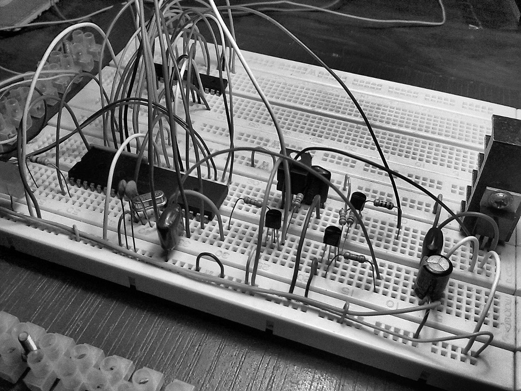 |
| Prototyping version of AVR-HV programmer |
This project is hosted at sourceforge.net and all the project files, schematics, PCB design files, source codes and compiled binaries are available to download at there. Complete documentation is also available at project wiki section.
Current version of AVR-HV support ATmega series of AVR microcontrollers, but it can also be used with ATTiny microcontrollers which having high voltage parallel programming (HVPP) interface. To introduce new devices, only the configuration file need to be change and no source code changes are necessary.
 |
| AVR-HV Windows GUI |
This project is an open source hardware (OSHW) project. AVR-HV source codes and compiled applications (including firmware) are released under the terms of MIT Licenses. AVR-HV USB programmer design files and AVR-HV documentation are released under the terms of Creative Commons Attribution 4.0 International License.
Comments