This is 5V 3A power supply to drive two USB based devices simultaneously. This power supply is design around LM2576-5.0 switching regulator IC and the main reasons to choose this IC is its low parts count, small heat sink requirements and its inbuilt current limit protection feature.
We specially design this power supply to work with development boards / single board computer (SBC) platforms such as Raspberry Pi, Banana Pi, BeagleBone, etc. This power supply can also be used to provide power to USB OTG peripherals over USB Y cables. We test this setup and got successful results with Huawei Ascend P6 mobile phone.
The schematic of this power supply is based on sample circuit explained in LM2576 datasheet. In this power supply the most difficult part to obtain is 100μH inductor. In our prototype we wind this inductor by ourselves and those winding details are illustrated and described in below.

The 100μH inductor used in our prototype is built around "King Magnetics" toroidal core (Part No: N20x12x8). The core which we used is covered with plastic jacket for mounting purposes, but that "mounting unit" is not mandatory for our PCB design. Dimensions of the toroidal core are illustrated in above diagram. We wind 50 turns of 1.045mm Ø insulated copper wire on this core and we got 102.4μH reading with is coil. Both IC1 and DB1 (D3SB20 bridge rectifier) need heat sinks.
The PCB, schematic diagram and more information about this power supply unit are available at google drive.
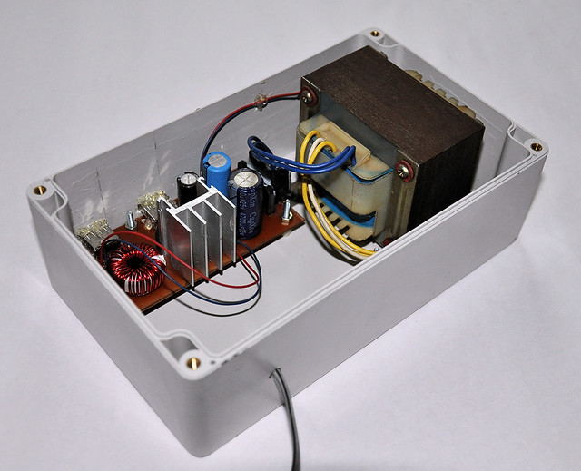 |
| Prototype version of 3A USB power supply |
We specially design this power supply to work with development boards / single board computer (SBC) platforms such as Raspberry Pi, Banana Pi, BeagleBone, etc. This power supply can also be used to provide power to USB OTG peripherals over USB Y cables. We test this setup and got successful results with Huawei Ascend P6 mobile phone.
The schematic of this power supply is based on sample circuit explained in LM2576 datasheet. In this power supply the most difficult part to obtain is 100μH inductor. In our prototype we wind this inductor by ourselves and those winding details are illustrated and described in below.
The 100μH inductor used in our prototype is built around "King Magnetics" toroidal core (Part No: N20x12x8). The core which we used is covered with plastic jacket for mounting purposes, but that "mounting unit" is not mandatory for our PCB design. Dimensions of the toroidal core are illustrated in above diagram. We wind 50 turns of 1.045mm Ø insulated copper wire on this core and we got 102.4μH reading with is coil. Both IC1 and DB1 (D3SB20 bridge rectifier) need heat sinks.
The PCB, schematic diagram and more information about this power supply unit are available at google drive.
Comments