Mullard 3-3 is quite popular 3W tube amplifier introduced by Mullard Ltd in 1956. A schematic and design detail of this amplifier is available in "Mullard Circuits for Audio Amplifiers" book and in National Valve Museum article. This amplifier is based on EF86, EL84 vacuum tubes, and EZ80 full wave rectifier tube. In this project, we decided to construct this original Mullard 3-3 Amplifier with some slight changes and commonly available electronic components.
In our prototype, we replace the EZ80 tube with 400V 5A bridge rectifier which is commonly available in many electronic spare parts shops. Also, we replace EL84 with 6P14P pentode and EF86 with a 6J8 pentode. Both of these valves can directly use with this circuit and those values are available for a lesser price than EL84, EF86 tubes.
Except for the above changes, we slightly change some values of resistors and capacitors due to their unavailability in the local market. Those modified values listed in the below table:
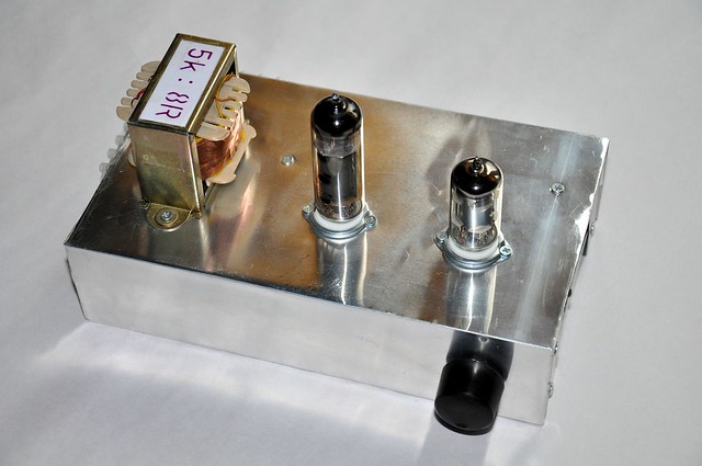 |
| Top view of Mullard 3-3 amplifier with 6P14P and 6J8 tubes. |
In our prototype, we replace the EZ80 tube with 400V 5A bridge rectifier which is commonly available in many electronic spare parts shops. Also, we replace EL84 with 6P14P pentode and EF86 with a 6J8 pentode. Both of these valves can directly use with this circuit and those values are available for a lesser price than EL84, EF86 tubes.
Except for the above changes, we slightly change some values of resistors and capacitors due to their unavailability in the local market. Those modified values listed in the below table:
| Component | Value |
|---|---|
| R4 | 100Ω (1W) |
| R13 | 470Ω (5W) + 100Ω (5W) resistors in series |
| R15 | 470Ω |
| RV1 | 1MΩ |
| C2, C5 | 330pF / 2kV |
| C6, C9 | 47µF / 400V |
| C8 | 22µF / 100V |
| C10 | 10µF / 400V |
The next most important component is the Audio output transformer. Due to limited availability, Audio output transformer is now expensive to purchase and costs more than Rs. 3000 (22USD at the time of writing). Because of this reason, we decided to construct the output transformer by ourselves and its input parameters and winding details are listed below:
| Parameter | Value |
|---|---|
| Supply voltage | 300V |
| Output power | 3W |
| Primary impedance | 5000Ω |
| Output impedance | 8Ω |
| Core size | 0.3 inch2 |
| Primary winding | 6435 turns using 36 S.W.G enameled copper wire |
| Secondary winding | 257 turns using 27 S.W.G enameled copper wire |
For the above calculations, we use audio output transformer winding calculator script, which is available in here.
We assemble this amplifier on home-made aluminum chassis and tag-board is constructed on a PCB. As shown in photographs for some components we use point-to-point wiring.
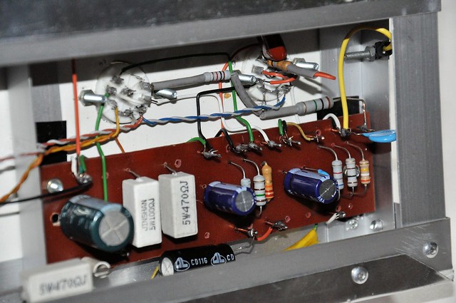 |
| Bottom view of the prototype amplifier. |
In our test arrangement, we power this amplifier with our lab PSU and the results were astounding. For this test setup, we use the 8-inch 8R full range speaker and PC sound card as an audio input source.
In the next stages, we plan to construct mains transformer, PSU and cabinet for this amplifier.
Comments