Star test is the most recommended method to test and collimate telescopes. To do a "star test" we need to aim and track telescope with real star and most of the times this is quite difficult to do because of the fast movement of stars and bad sky conditions. Another problem with the real star is air turbulence and some times this effect may lead to false conclusions.
However artificial star is an excellent alternative for "real star test" and in this post, we introduce easy to build "artificial star unit" to test and collimate telescopes. This unit is based on commonly available electronic components and it can operate with a 9V battery. At the time of writing this unit can build around LKR 1000.00 (Approximately 7.00 - 8.00 USD).
In this given design, we use NE555 timer IC to generate PWM output to LED and this allows us to control the intensity of the artificial star. In our prototype we use high-bright 3mm white LED as our light source.
Apart from the circuit, the next most important thing in this unit is it's LED mounting. Since real star appears like "point of light" this artificial star must appear as a point of light. To archive this same effect we dill 300 microns (0.3mm) pin-hole in our casing as shown in below.
We test and collimate several telescopes with this unit, which including 8'' and 10'' Newtonians, 6'' and 11'' Schmidt-Cassegrain telescopes. Now we use this unit periodically to test our scopes for collimation and related issues.
PCB, schematic and wiring diagrams of this "Artificial Star Unit" is available to download at google drive.
However artificial star is an excellent alternative for "real star test" and in this post, we introduce easy to build "artificial star unit" to test and collimate telescopes. This unit is based on commonly available electronic components and it can operate with a 9V battery. At the time of writing this unit can build around LKR 1000.00 (Approximately 7.00 - 8.00 USD).
In this given design, we use NE555 timer IC to generate PWM output to LED and this allows us to control the intensity of the artificial star. In our prototype we use high-bright 3mm white LED as our light source.
Apart from the circuit, the next most important thing in this unit is it's LED mounting. Since real star appears like "point of light" this artificial star must appear as a point of light. To archive this same effect we dill 300 microns (0.3mm) pin-hole in our casing as shown in below.
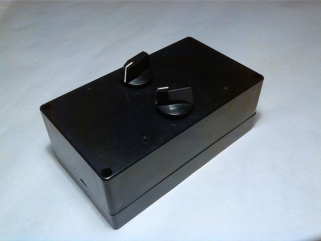 |
| A prototype version of the artificial star unit. Output pin-hole is located in the left side of this box. |
We test and collimate several telescopes with this unit, which including 8'' and 10'' Newtonians, 6'' and 11'' Schmidt-Cassegrain telescopes. Now we use this unit periodically to test our scopes for collimation and related issues.
PCB, schematic and wiring diagrams of this "Artificial Star Unit" is available to download at google drive.
Comments