
Replacement motor driver for mini drills

In my workshop, I got a couple of INGCO power tools. INGCO is a Chinese power tool manufacturer, and this brand is quite popular in Sri Lanka. Out of those tools I frequently used INGCO MG1502.2 mini drill. I purchased this drill three years back and mainly use for engraving and for precision drilling.

A few days ago while I'm using this drill, it suddenly stopped. As a first thing, I checked brushes and mains-lead. After a few minutes of inspections, I found out that both brushes and mains lead are in perfect order. To further examine I decided to open the drill.

The internal layout of this drill is quite simple. It mainly consists of an AC motor and electronic speed controller circuit. After a few checkups, I determined that the electronic speed controller is dead. In speed controller board I notice some unknown microcontroller, 74HC595 shift register, and Z0409MF TRIAC. As like many Chinese products here also they erased the IC number and other markings of the MCU. After examining all the components, I concluded that the problem is in this MCU.

Damaged MG1502.2 motor driver.

Because the MCU is unknown, I decided to create my own controller to drive this drill. Due to limited space, I choose PIC12F series MCU for this controller. I used this MCU for zero-crossing detection, determine TRIAC firing times and to handle buttons and switches.

New PIC12F629 based motor speed controller

To drive the motor I choose BT134-600 TRIAC. The controller's supply comes from the mains through a simple RCD circuit. With the help of the inbuilt peripherals of PIC12F629 MCU, I build this controller with few external components.

The firmware of this controller is design to operate with 4MHz internal-oscillator of the MCU.

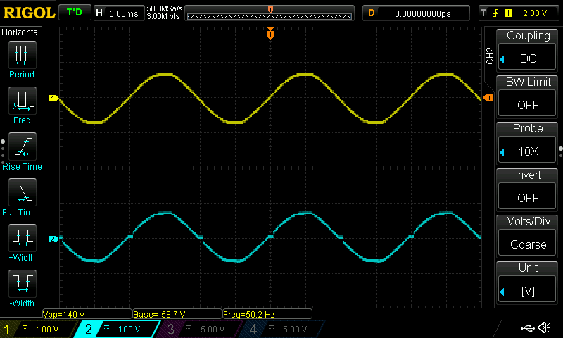
AC line waveform on minimal speed setting.

AC line waveform on maximum speed setting.

To design the PCB, I refer to the dimensions of the original controller board. To reduce installation problems I also placed all switches and connectors in the corresponding places as original board.

This controller board is powered by AC mains voltage. Avoid touching the board when power is applied. If possible, use an isolation transformer for the testing.

Installed driver PCB.

After installing this controller drill start to work again. The lowest speed which I set in firmware is not much use with the load. Besides that, this controller works as similar to the original controller.

View of the final assembly.

The schematic, PCB design files, firmware source code and compiled binaries related to this project are available at my GitHub repository.

Comments

Popular posts from this blog

CD2003 - yet another simple FM radio receiver

In the last few days, we are looking for some simple FM radio receiver to integrate into one of our ongoing projects. For that, we try several FM radio receiver ICs including TDA7000, CD2003/TA2003/TA8164, CXA1019, and KA22429. Out of all those chips we select CD2003 (or TA2003/TA8164) based receiver for our project because of its simplicity and outstanding performance. Except to CD2003, Sony CXA1019 also perform well but we drop it because of its higher component count. We design our receiver based on Toshiba TA2003 datasheet and later we try TA8164 and CD2003 with the same circuit. Either CD2003 or TA8164 can directly replace TA2003 IC, and as per our observations, TA8164 gives excellent results out of those 3 chips. A prototype version of CD2003 FM radio receiver The PCB design and schematic which we used in our prototype project are available to download at google drive (including pin-outs of crystal filters and inductors ). Except for CD2003 IC, this receiver consist...

Arduino superheterodyne receiver

In this project, we extend the shortwave superheterodyne receiver we developed a few years ago . Like the previous design, this receiver operates on the traditional superheterodyne principle.  In this upgrade, we enhanced the local oscillator with Si5351 clock generator module and Arduino control circuit. Compared to the old design, this new receiver uses an improved version of an intermediate frequency amplifier with 3 I.F transformers. In this new design, we divide this receiver into several blocks, which include, mixer with a detector, a local oscillator, and an I.F amplifier. The I.F amplifier builds into one PCB. The filter stage, mixer, and detector stages place in another PCB. Prototype version of 455kHz I.F amplifier. In this prototype build, the Si5351 clock generator drives using an Arduino Uno board. With the given sketch, the user can tune and switch the shortwave meter bands using a rotary encoder. The supplied sketch support clock generation from 5205kHz (tuner f...

Experimental narrowband FM receiver for 2-meter band

This project is about MC3362 and ADF4351 based modularized, 2-meter narrow band FM receiver. In this design, the receiver splits into three modules as RF preamplifier, MC3362 tuner, and ADF4351 oscillator. The RF preamplifier builts around BF900 dual-gate MOSFET. The tuner stage builts using the popular MC3362 , low power narrowband FM receiver IC. For the oscillator, we use the ADF4351 DDS RF signal generator module. The core component of this receiver is MC3362 IC. This IC was designed by Motorola and is no longer in production, but this IC is still available to purchase in many online stores . The chip we used in this receiver was purchased from a local electronic component store for LKR 75 (USD 0.2). The RF preamplifier used in this receiver extracts from the N.Ganesan's (VU3GEK) LRR200, 2-meter band FM receiver project . Prototype version of the RF preamplifier. In this prototype, the above preamplifier was built as a module using a Manhattan construction technique. Th...